Today, proper maintenance and management of deteriorating infrastructure under tight budget constraints, have become serious problems for bridge owners. The condition of highway bridges has traditionally been monitored by visual inspection whereby structural deficiencies are manually identified and classified by qualified inspection personnel. However, the quality of the control results obtained through the traditional approach depends on the subjective judgment of individual inspectors based on their knowledge and experience.
In addition, these traditional control procedures require proper investment in both time and labor costs. These factors support the need for research and development of more reliable, objective, and effective bridge inspection methods. Qualified inspectors perform traditional on-site inspections up-close visual inspections and sound tests often from a crane suspended lifting cages or built-in inspection stage; which likely exposes inspectors to some security risks.
Safer inspection methods require new innovations in bridge inspection technology. In addition, there will be new technologies that improve inspection efficiency to help address the upcoming shortage of qualified bridge inspectors. A bridge inspector’s duties include preparing a bridge summary condition factors that by their nature reflect the engineering of the individual inspector’s judgment. If we can improve the efficiency of data collection and reduce the time required of inspectors in the field to make an assessment of the general condition of the structure, more time will be made available to the same inspectors to carry out detailed practical tests and inspections of those pre-shielded bridge elements where structural defects require special attention.
1.1 Inspection Methods Using High-Definition Video (HDV):
Recently, research and development of crack detection methodologies for efficient inspection of highway bridges using digital images of the structures, we have seen significant technological advances. In the past, conventional control techniques with the use of digital image processing had not been widely applied for practical use because of their limited image quality. The equipment was typically expensive, and its use was limited mainly to technical research and special forensic professional services. However, recent innovations and improvements in image quality and data processing technologies have significantly contributed to the technical viability of this new technology.
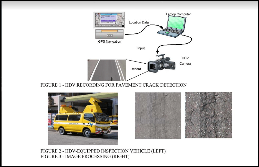
FIGURE 1 shows the mechanism of pavement crack detection using HDV. The
technology is a combination of GPS, geographic information system (GIS), and HDV images. The GPS navigation system, HDV, and laptop are included inside the vehicle. An HDV camera is attached to the top of the inspection vehicle in order to record the surface condition (FIGURE 2).
This Recorded data is analyzed by image processing to determine the state of the individual structure in relation to the size of the crack, location, and distribution. These detected cracks are identified in the digital crack map. The Crack size and length are determined by the computer software and these quantitative characteristics are also summarized in a spreadsheet format. The crack maps and related data are then provided to engineers for their subsequent structural diagnosis and rehabilitation planning. A significant advantage of HDV technology with respect to crack identification and measurement is the ease of maintaining historical records of bridge cracks for use while tracking crack propagation over time. Image processing involves a two-gradation analysis and line analysis. The first step of the two-gradation analysis converts a digital image into binary (black and white) data by the analysis of the degree of color transition from nearby pixels, which allows our computer program to distinguish the spectrum and identify individual cracks. Then the second step identifies lines of black pixels to confirm the existence of cracks (see FIGURE 3).

1.2 Inspection Method Using Infrared (IR) Imagery Technology:
Infrared imagery technology is a non-destructive testing method to locate possible de-lamination and spalling of concrete by the monitoring of temperature variations on a concrete surface using infrared thermography technology.
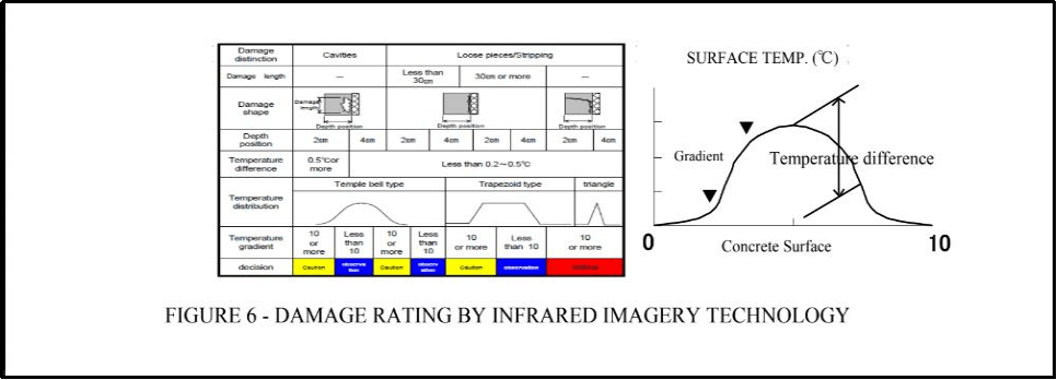
IR technology offers inspection personnel the advantage of being able to identify likely delaminated, spalled, and inner void areas from a distance of up to 5 meters with reasonable accuracy; thus avoiding the time and expense of gaining immediate access to the concrete surface to conduct conventional sounding tests. The results of IR images provide bridge owners with a reliable screening of potential concrete defects on concrete structures that have been traditionally obtained by more time-consuming (and also very expensive) sounding tests. By applying this technology to the concrete inspection process, personnel can focus their hands-on sounding test activities on those areas shown through IR imaging as likely to be defective.

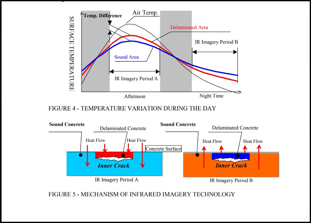
FIGURE 4 shows the mechanism of the Infrared thermography method. The red line shows the daily temperature variation for delaminated concrete, while the blue line shows the daily temperature variation for concrete in good condition. The delaminated concrete surface shows different temperature variations (see FIGURE 5).

IR technology is applicable during the periods when temperature differentials are detectable over time (IR imagery periods A and B in FIGURE 4). In Japan, spalling of concrete debris from expressway bridges has become a serious issue. In order to prevent hazards to third parties, comprehensive sounding tests have been performed on all potentially hazardous concrete surfaces exposed to motorist and pedestrian traffic. Using IR thermography technology, engineers can check the delamination and/or spalling of concrete about three times faster than they can by conducting conventional sounding tests because IR technology applications require significantly less staging to secure adequate site access and correspondingly less traffic control to collect the required field data. Concurrently IR versus conventional sounding tests offers a 40% cost saving.
1.3 Combination of HDV And IR Imaging Technology
HDV technology provides visual digital information to bridge inspectors, and conditions of the concrete surface, which were traditionally obtained from detailed view controls. The IR display technology also corresponds to the sound system tests traditionally used to detect voids, delaminations, and/or areas of crushed concrete.
Most information from visual inspection and sounding tests can be obtained by combined HDV and IR inspection imaging technology. IR technology provides over 95% accuracy. An effective combination of these technologies can contribute to this reduced time for on-site inspection and preparation of the inspection report, which allows engineers to have more opportunities to lean on technical problems such as structural diagnosis and strategic rehabilitation planning.
Below is the benefits use of new control technology:
– Minimization of human error factors (improving objectivity)
– Providing a digital record to compare historical inspection data
– Improve efficiency in the application of bridge inspection resources
1.4 Potential Applications Of HDV And IR Imaging Technologies
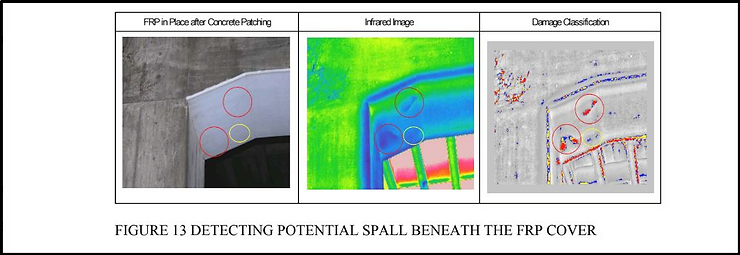
HDV and IR imaging technologies can be used for both operating bridges inspection and inspection of new constructions in terms of compliance with the specification (in terms of cracks percentage of the area) at the time of handover of the building. HDV technology was also successfully used to support night lane reflectivity tests. IR image technology has many other uses as well. Among maintenance-critical applications and rehabilitation is the ability to use infrared imaging to monitor areas of structural distress which were covered with fiber-reinforced polymer (FRP) materials (see FIG 13).

Another application is the identification of subsurface irregularities (stones covered with grout pockets) in the new structural structure immediately after removing the formwork.
Conclusion
Using the newly proposed HDV and IR technology, bridge engineers can quickly and efficiently obtain objective current information about the condition of the bridge, which was conventionally obtained through time-consuming methods and in some cases more subjective detailed visual inspections and sounding tests.
The digital output of these HDV and IR inspection techniques is improving safety and objectivity and contributes to the improvement of inspector efficiency by significantly reducing on-site inspection and time in the field.
However, it should be noted that while HDV and IR technologies offer new effectiveness in the bridge inspection process, they do not replace inspectors carrying out specific follow-up actions on-site and a detailed survey of the structure. While improved efficiency of bridge inspection caused by HDV application and IR technologies bring significant benefits to the overall bridge inspection process, they are not a substitute for the ongoing need for experienced engineering judgment.
Currently, the costs of traditional and new control technologies are similar. The lower cost of field data collection with the new technology is somewhat offset by the additional cost for computer-aided analysis. With the likely improvements in computer technology, new inspection technologies will become more cost-effective in the near future.
